
A Brief Discussion on the Structural Design of Checking Fixtures for Automotive Parts
With rising consumer spending power, demands for automotive functionality and styling are increasing, and the pace of new model development and introduction is accelerating, leading to higher requirements for the assembly relationships of automotive body panels. The precision of individual automotive body panels determines whether assembly design standards can be quickly met. The key to parts quality control lies in the accurate and rapid inspection of stamped body panels. Currently, checking fixtures are the most important professional measuring equipment for inspecting the precision of body panel parts; therefore, the design and application analysis of automotive body panel inspection fixtures is essential.
Checking Fixture Design Standards During the introduction of new models, checking fixtures must be designed based on parameters such as the new model’s product model, GD&T drawings (automotive body panel tolerance standards), and general checking fixture design standards (which vary from manufacturer to manufacturer) to meet the styling and precision tolerance requirements of the new model’s body panel parts.
Currently, the main equipment for inspecting the precision of vehicle parts includes blue light scanning equipment (a), coordinate measuring machines (b), and dedicated checking fixtures (c), as shown in Figure 1. For rapid inspection, dedicated checking fixtures are typically used for primary measurements, while blue light scanning equipment and coordinate measuring machines (C) provide auxiliary measurements. This analysis focuses primarily on the design and application of dedicated checking fixtures.
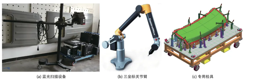
Figure 1. Inspection Equipment for Vehicle Part Precision
The design of vehicle part checking fixtures mainly considers the following aspects: ① The placement angle of the part on the fixture; ② The positioning principle of the part on the fixture; ③ The rationality of the fixture tolerance setting; ④ The applicability of the fixture structural design; ⑤ The marking and maintenance of the fixture.
As a specialized inspection device for measuring and measuring the precision of parts, checking fixtures are currently used by most automotive OEMs for part precision measurement. Because the precision requirements of various stamped automotive parts are high, they are usually controlled with an error unit of “0.01mm”. Each part, through assembly, ultimately achieves the requirements of the vehicle’s appearance and assembly relationship. If the error deviation of the parts accumulates, it may eventually lead to the overall precision of the assembly or the entire vehicle exceeding the design standard, affecting the appearance and function of the vehicle.
Checking Fixture Manufacturing
⑴ Structural Frame
① Fixture Base. Usually welded from square tubular profiles or channel steel. The fixture base should have sufficient rigidity, strength, and stability to ensure that it does not deform under normal use. Diagonal bracing is welded to necessary parts to increase strength, and the entire base should undergo artificial aging treatment.
② Reference plate. Typically 20-30mm thick, made of 45# steel. The entire base must undergo artificial aging treatment to ensure strength and rigidity that the fixture will not deform under normal use.
③ Support frame of the fixture, composed of square tubing or cast aluminum, should ensure complete support for the fixture. The frame should have sufficient rigidity, strength, and stability, and the entire frame should undergo stress-relief treatment.
④ Fixture. Usually designed with resin based on the product’s shape. A “0mm” surface is designed for positioning, support, and clamping points; a “3mm” surface is designed as a measurement reference value for clearance surfaces, inspection surfaces, and contours.
⑤ Measuring fixtures. Based on the tolerance standards of the part’s cover, measuring fixtures for gaps, surface differences, trim lines, and holes are designed at corresponding locations, such as inspection blocks, clamping plates, fixture reference lines, and holes, to facilitate rapid measurement of corresponding tolerance values using the references on the fixture.
⑥ Auxiliary components. To facilitate the placement and movement of the fixture, the design should consider the installation of casters, adjustment support blocks, forklift slots, etc., and the overall weight should be considered based on the transfer device.
⑵ Reference Blocks. Typically, corresponding reference blocks are designed on the upper surface of the fixture, as shown in Figure 2. Reference blocks usually include a first set and a second set of reference blocks, serving as a reference for calibration of measuring tools and fitting to scanning analysis equipment (the specific design varies from manufacturer to manufacturer).
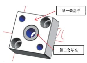
Figure 2 Fixture Reference Blocks
① First Set of Reference Blocks. Machining reference blocks are installed at appropriate locations on the flat plate of the fixture base in the three directions (X, Y, Z). Reference values should ideally be multiples of 10 (preferably multiples of 50), and are installed using a two-pin, two-anchor mounting method.
② Second Set of Reference Blocks. Measurement references are installed on each reference block of the first set of reference blocks, with an inner hole roughness of R0.8μm. The reference sleeves and reference blocks are tightly fitted; copper pads and adhesive bonding are not permitted.
Each reference block must be fitted with a protective cover (made of soft plastic), and a nameplate should be prominently displayed nearby to indicate the theoretical coordinate values for machining and measuring the vehicle. The maximum spacing between each side of the reference blocks should be 1 meter to facilitate subsequent use of blue light scanning equipment or a coordinate measuring machine (CMM) for part fitting.
⑶ Part Positioning.
① Pin Positioning. To ensure stable part positioning, parts with positioning holes or mounting holes typically use primary and secondary pin positioning. Primary pins are generally cylindrical (the form varies between manufacturers; some manufacturers use tapered pins), and secondary pins are diamond-shaped, as shown in Figure 3.
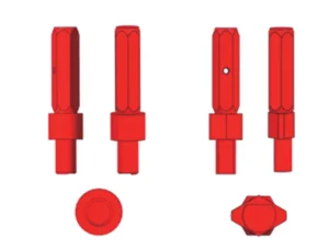
Figure 3 Primary and Secondary Pin Forms
② Contour Positioning. Contour positioning is not supported separately but directly fixed to the upper surface of the detection block. The forward and backward direction can be adjusted using shims, as shown in Figure 4.
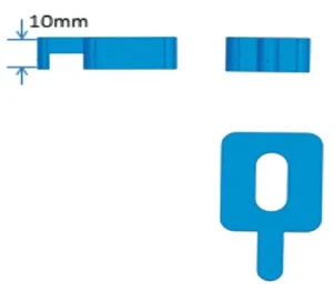
Figure 4 Contour Positioning
⑷ Design of Part Surface and Line Measurement Methods.
The inspection of part surfaces and lines is judged based on the fit between the part and the molded surface. Figure 5 lists three design types: Type I selects method 1; Type II prioritizes method 2; if not feasible, choose method 3; Type III can select 4, 5, or 6 based on measurement convenience.
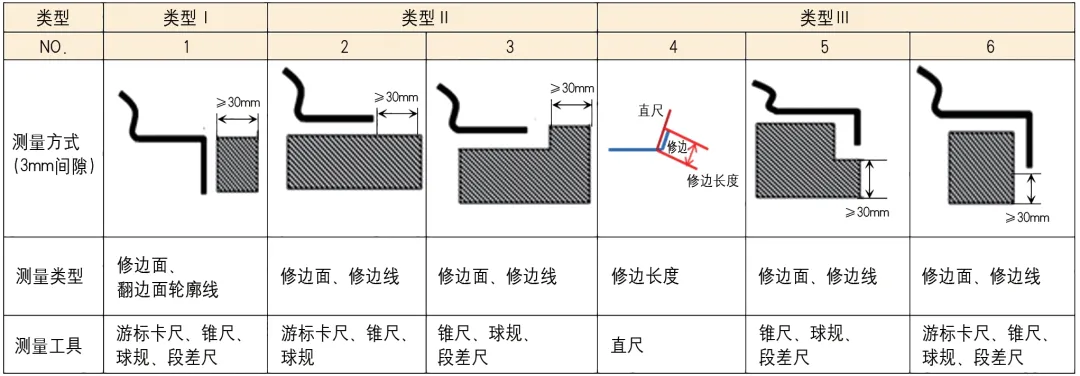
Figure 5. Measurement methods for part surfaces and lines
(5) Quick-clamp design.
Generally, the design is based on the requirements of the product tolerance drawings. The bottom clamping head should have a rubber buffer block to prevent excessive clamping force from damaging the part. The top gripper position should have a heat shrink sleeve. The quick-clamp must ensure convenient clamping and no interference with other components.
(6) Transfer fixture design.
To facilitate the placement and movement of the fixture, the design should consider installing four casters, two of which should be swivel casters with locking function. A forklift slot should be provided. The structure of the forklift slot must ensure functional and strength requirements, while not affecting the calibration of the fixture. If the forklift slot is at the lower end of the base, it needs to be made into a detachable bolt-mounted design to ensure the placement of the fixture during processing and measurement.
Measuring Tools and Fixtures
Common Measuring Tools
The commonly used measuring tools for precision measurement and analysis of stamped parts include feeler gauges, go/no-go gauges (Figure 6), ball gauges, clearance gauges, surface difference gauges (Figure 7), and vernier calipers (Figure 8).
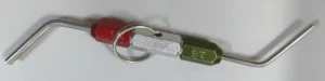
Figure 6 Go/No-Go Gauge
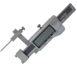
Figure 7 Surface Difference Gauge
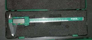
Figure 8 Vernier Caliper
Hole Inspection
① Functional holes and mounting holes are usually inspected using position pins.
② General holes and flanged holes are generally inspected using scribing. Single or double scribing can be used depending on the hole size. If using a single scribing, the scribing diameter is the same as the hole diameter being inspected; if using double scribing, the outer scribing is the same as the hole diameter being inspected, and the inner scribing is 3mm smaller on one side than the hole diameter being inspected.
③ For pin inspection holes on fixtures, a composite pin is used, with one end being a go/no-go pin and the other end being a scribing pin. If the go/no-go pin fails the inspection, the deviation is measured using the scribing pin.
Step difference inspection of trimming line and flanged surface:
① Trimming line and flanged surface are usually inspected using two lines: “0mm” and “+3mm”. The surface with the engraved lines should be 15mm outward from the “0mm” line to meet measurement space requirements.
② The flanged height of the part is inspected using the “0mm” and “3mm” engraved lines of the mold, the 3mm gap of the mold, and a ruler or vernier caliper for inspection. For parts with large outer panel springback, it is recommended to use a ruler or vernier caliper for inspection to avoid the influence of springback. The key points of operation are that the ruler or vernier caliper angle is parallel to the flange, with the bottom end against the bottom of the inner side of the flange, to measure the flange height and compare it with the value of the product’s digital model.
Surface inspection: Surface differences around the product are mostly inspected using the “3mm” gap as the reference surface in conjunction with gap gauges, feeler gauges, or ball gauges. Alternatively, a testing block can be used as a reference surface, measuring the surface difference using the “0mm” surface, as shown in Figure 9. For critical surfaces or features in the middle of a product that require inspection due to their mating relationship, a clamping plate is used for inspection. The measurement reference value is typically 3mm, as shown in Figure 10.
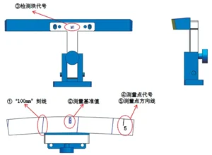
Figure 9 Inspection Block
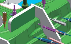
Figure 10 Clamping Plate
Conclusion Automotive OEMs have high requirements for vehicle styling and fit, thus demanding increasingly higher precision from parts. This necessitates specialized measuring tools with high stability and rapid inspection capabilities, playing a decisive role in controlling vehicle body quality. Improving inspection tool technology and cultivating skilled personnel are crucial. Persistent efforts are needed to develop inspection tools suitable for the specific characteristics of various automotive OEMs and to standardize inspection tool design.